Home Page: ECE 304
Outside
............................................
PSpice.ini file for setting Probe colors
![]() (Right-click
on Hyperlink and Save Target
As to load to disk)
(Right-click
on Hyperlink and Save Target
As to load to disk)
(last updated Saturday, January 21, 2006 )
Link to a modified PSpice.ini file
You may not wish to incorporate all the changes in the ini file linked above.
However, to allow importation of PROBE plots into WORD, the following changes
to the PSPICE.ini File normally located at C:\Program Files\OrcadLite\PSpice\PSpice.ini are suggested:
[PROBE DISPLAY COLORS]
NUMTRACECOLORS=12
BACKGROUND=Brightwhite
FOREGROUND=Black
TRACE_1=LightBlue
TRACE_2=Blue
TRACE_3=DarkBlue
TRACE_4=Orange
TRACE_5=Red
TRACE_6=DarkRed
TRACE_7=DarkGreen
TRACE_8=BrightGreen
TRACE_9=Pink
TRACE_10=LightGray
TRACE_11=DarkGray
TRACE_12=Purple
TraceWidth=4
The TraceWidth is set to make the default curve width in Probe a bit heavier.
That makes plots easier to read when copied into Word.
You may wish to change the default labeling for voltage and current.
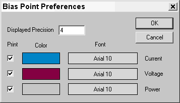
For that, select PSpice/Bias Points/Preferences to find this menu:
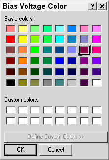
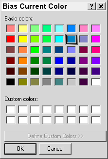
Clicking on the colored squares, my choice for tag colors is shown below.
These colors print well when schematics are copied into Word. The font also can be set.
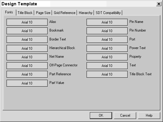
You may also want to change the font size on your schematics.
To do this, choose Options/Design Template, and fill in the menu shown below.


